


Drastically Reduce Man-Hours Spent on Reverse Engineering Through Partial Reverse Engineering Features
Are you spending too much time reverse engineering from point cloud?
If a CAD data exists, point cloud data and the CAD data can be compared so that only the surfaces that are different can be reconstructed. Since only the differences are reverse engineered, the man-hours can be significantly reduced compared to reversing the entire model.
In spScan, this is called “partial reverse.” In “partial reverse,” new surfaces are created so as to be continuous with the surrounding surfaces, while maintaining the tolerable distance.
What is partial reverse engineering?
- Partial reverse engineering imports CAD data and reverses only the area deviated from the measurement data.
- With the required minimum reverse engineering, man-hour can be greatly reduced.
- The following methods for partial reverse engineering are available in spScan.
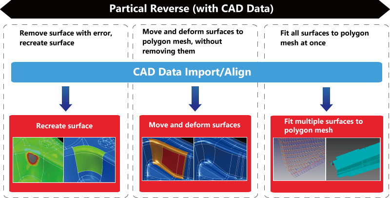
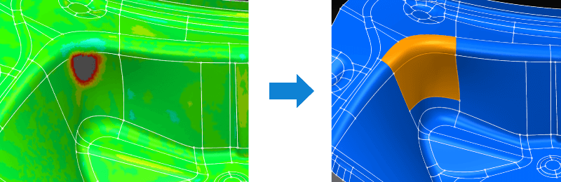
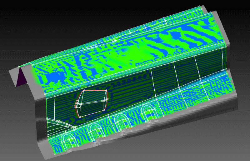
Recreating surfaces
Remove surfaces with errors and recreate those surfaces.
- Check for errors between the surfaces and the polygon mesh to create only the surfaces in locations with errors.
- By setting creation conditions such as distance from the polygon mesh, you can create continuous surfaces to the original adjacent CAD surfaces.
- Even if the surface configuration was changed from the original CAD shape, you can still create new surfaces while checking for deviation from the polygon mesh.
- Because it is possible to easily restore the shape with a large distance error to the polygon mesh, the partial reverse engineering is the most used method.
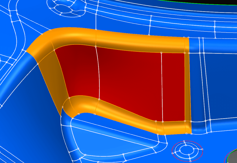
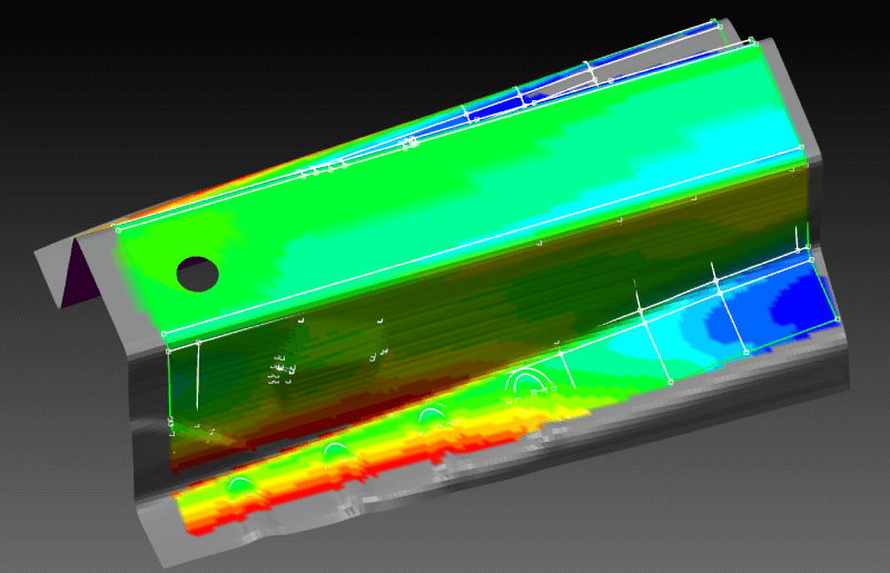
Moving and deforming surfaces
Move and deform surfaces to minimize deviation from the polygon mesh without removing the deviated surfaces. (surface optimization tool)
- Optimize CAD surfaces to minimize distance errors (parallel translation, rotation, and offsets) to the polygon mesh.
- Optimization can be specified for multiple surfaces. If a moving amount is specified for optimization, the surface will only be moved and not deformed while preserving the original shape of the surface configuration.
- However, the surfaces (orange surfaces) adjacent to the optimized surface (the red surface) can be deformed to keep continuity with adjacent surfaces by following the movement of the optimized surface.
- This can be applied as a method of partial reverse engineering if the distance error is small.
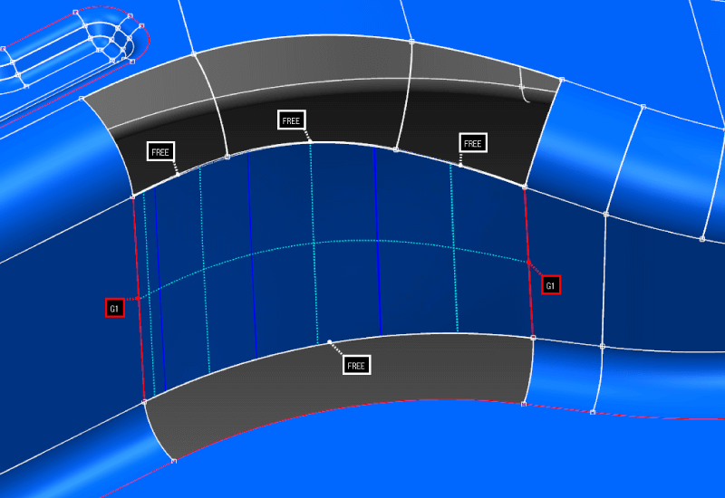
Surface deformation
Deform surfaces to minimize deviation from the polygon mesh and create smooth connections with adjacent surfaces without removing the deviated surfaces. (surface fitting tool)
- Deform the surface individually to minimize deviation from the polygon mesh while maintaining the specified continuity with adjacent surfaces.
- This tool can be applied when you want to partially modify the surface having a distance error to the polygon mesh.
Multiple surface fitting
Fit multiple surfaces at once to the polygon mesh.
- Fit multiple surfaces at once to the polygon mesh.
- This tool is effective if you want to recreate die data automatically and quickly from the data measured by a non-contact measuring device. You can recreate the shape of the die modified by hand on site in CAD.
However, the distances between surfaces will not be guaranteed. In some cases, it might also be impossible to follow the deformation if the amount of movement is large. If the deformation surface is defective, the surface will need to be modified.
tag : Partial reverse