


Create Spline Surfaces that can be Handled Easily by CAD/CAM/CAE

Are you able to use surfaces created with conventional reverse engineering tools for post operation processes such as for design and analysis?
spScan is a reverse engineering tool that can effortlessly create spline surfaces with CAD surface configurations from non-contact measurement point cloud data that are easy to handle in CAD/CAM/CAE.
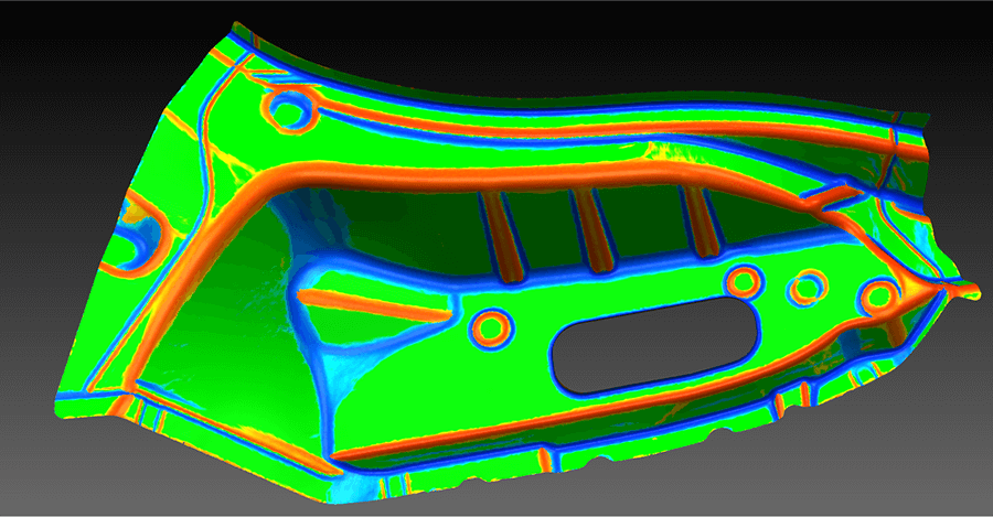
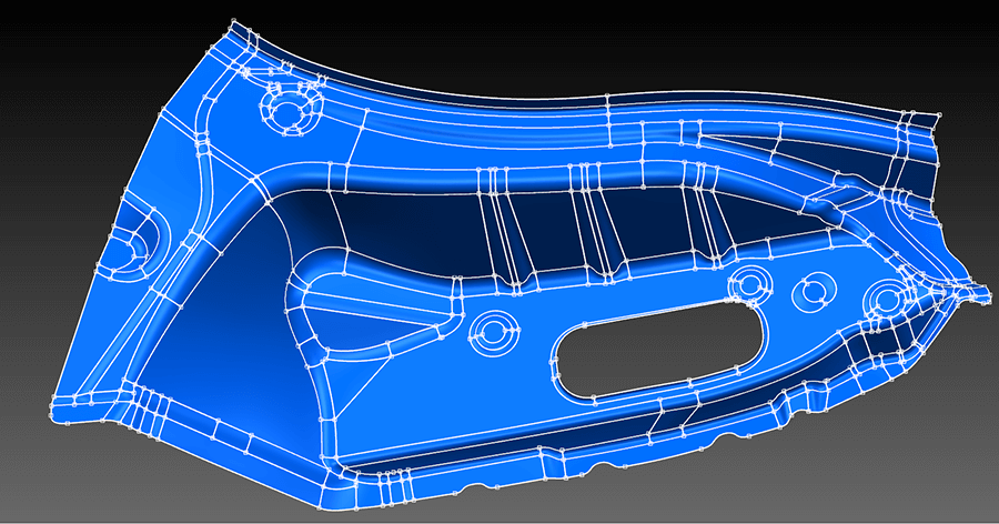
Display point cloud shape using curvature analysis color map. Using these colors, spScan can distinguish the surface construction and create surfaces (trimmed surfaces) by differentiated colors. The intended surface can be created readily according to purposes such as to “reproduce a faithful shape with little deviation from point cloud using surfaces” or “create a smooth surface with few control points.”
The created surfaces can be exported in a generic CAD format (IGES/STEP) and can be used in a CAD/CAM/CAE. Surface data resulting from reversing a solid shape can be utilized in a CAD system as solid data.
What is point cloud reverse engineering?
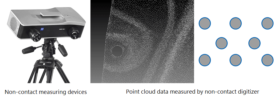
This is a technology for creating CAD data of the 3D surface shape from the measurement point cloud data obtained by measuring an actual mold, die or product with a non-contact measuring device, or the polygon analysis data from press forming simulation results or the strength analysis simulation results to utilize the data for design (CAD), machining (CAM), and analysis (CAE).
- The shape of the actual object in question is measured by non-contact measurement to create 3D point cloud data of the shape.
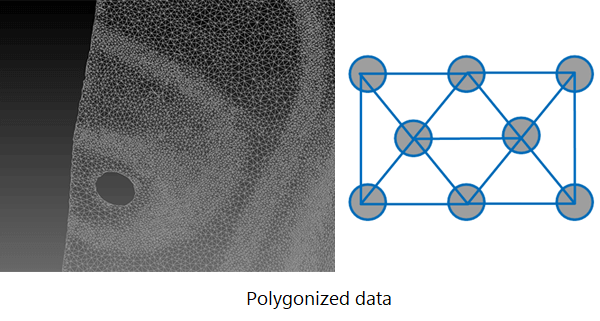
- Create three-sided polygon shapes from the point cloud.
- Create a NURBS surface from the polygon mesh.
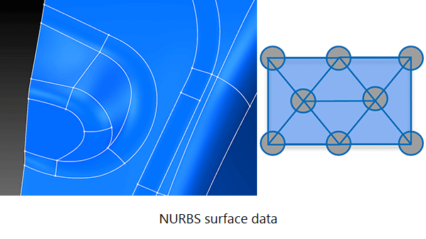
- Reverse engineered surface data is output in a generic CAD format as an IGES or STEP file.
spScan features
spScan is a tool specifically for reverse engineering that can easily create 3D spline surfaces
Example of surface creation method
When displaying the point cloud shape on the color map of a curvature analysis, the surface configuration is determined by colors allowing to easily create the surface (trim surface) in color unit.
During spline surface creation, a fitting accuracy to polygon mesh data can be specified
You can easily create surfaces in accordance with your purpose, which might be to visualize shapes faithfully using surfaces that hardly deviate from the point cloud, or to create smooth surfaces with few control points.
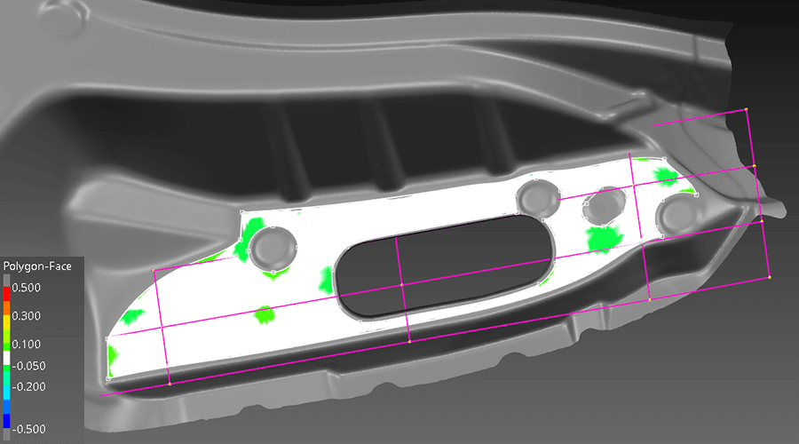
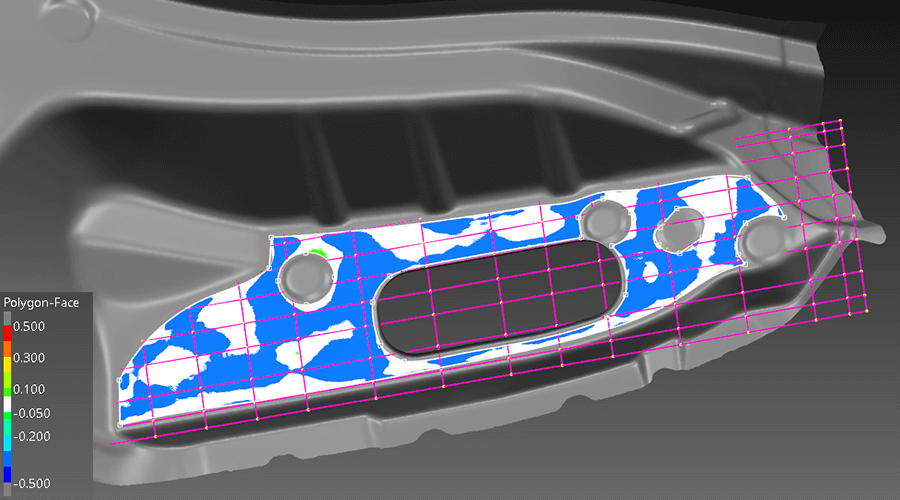
The following two images illustrate spline surface creation. The surface control points are displayed as a magenta grid. The surface with few grid arranged at equal intervals can be interpreted as smooth surfaces.
Trimmed surfaces are created within 0.1 mm and 0.05 mm of the distance error to a polygon mesh. In general, the smaller the distance error to the polygon mesh is specified, the more faithful surface for the polygon mesh can be create, but this tends to increase the control points of the surface.
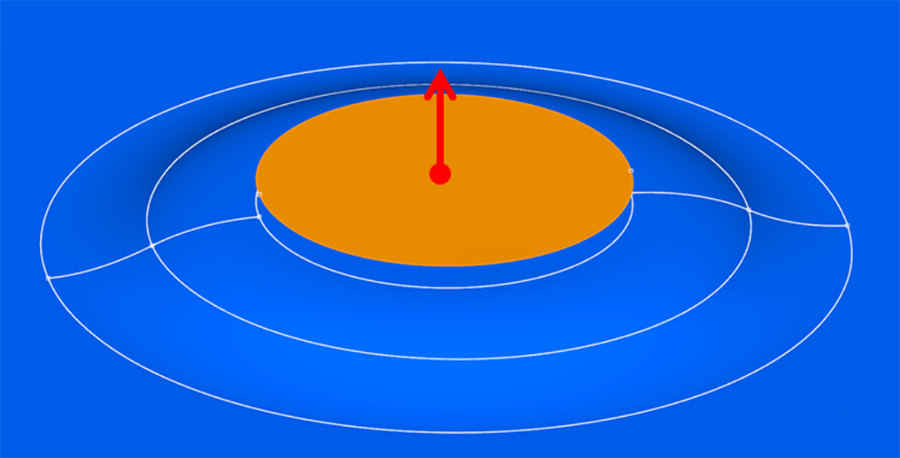
Reverse engineered surface data of CAD surface configurations can be edited with CAD/CAM/CAE software
For example, if you want to offset the shape of a seat by 1 mm due to a design change, you can import the reverse engineered surface shape into CAD and edit it directly to create the offset surface.
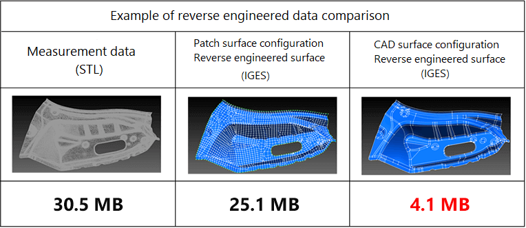
Reverse engineered surfaces with a lightweight data size can be created
Because spScan can create surface data of smooth CAD surface configurations with few control points, the data can be made more light-weighted in size than reverse engineered data of patch surface configurations.
The following chart provides an example of data size comparison when reverse engineered surfaces are exported in a generic CAD standard format, IGES. In this example, the data size of the reverse engineered surfaces configuring the CAD surface becomes more lightweight, approximately one-sixth of the size.
spScan is capable of free surface division (trimmed surface compatible)
Using a polygon mesh within a specified range, you can created trimmed surfaces from NURBS surfaces that satisfy creation conditions. By creating a base surface with a range wider than the specified polygon mesh range, you can create trimmed surfaces by polylines of a boundary of the polygon range.

We are creating various types of tools that enable auto processes.
Our goal for spScan is to develop tools that can perform batch auto processing to easily create the desired surfaces. We also provide technical support in response to user questions and requests for customized options that involve specific functions.
Cases in which spScan’s reverse engineering capabilities have been applied
- Reverse engineering molds
- Creating duplicate molds
- Data for modifying or recreating molds in the case of a mold fracture
- Providing feedback on expertise (shapes finished by hand on site)
- Digitizing the molds without data
- Creating estimated shapes
- Reverse engineering from design clay models
- Digitizing shapes created by designers
- Design study (Resolving of the problems quickly in a design stage)
- Analysis applications (strength, spring-back, wind tunnels, etc.)
- Utilized to review CAD models using CG
- Reverse engineering from products
- Performance evaluation of the prototype part and the mass production product
- Providing feedback on expertise (adjustments on site) for design
- Digitize and analyze other companies’ products to apply it to your own company’s product design
- Mold data creation
- Design imitation and reproduction
- Medical engineering – reverse engineering
- Reverse engineering and creating replicas of crafts, art, and cultural assets
- Reverse engineering from analysis
- Converting the expected spring-back shape of stamped products to CAD data and applying it to die creation
- Converting optimized shape meshes to CAD data and applying it to analysis tasks (wind tunnels, phase, and thickness)