


Use cases
Want to detect subtle deformations on surfaces. (Company B: Press Mold Manufacturer)

Leaving the subtle deformation on surfaces can cause serious issues in downstream processes. Why do subtle deformations on surfaces occur in the first place?
For the model created from scratch with CAD software, surfaces will not have any deformation unless the model was extremely unnatural. However, after performing forced deformations of surfaces such as springback compensation, the number of control points for surfaces is automatically increased causing surface deformation locally.
Various methods to detect surface errors
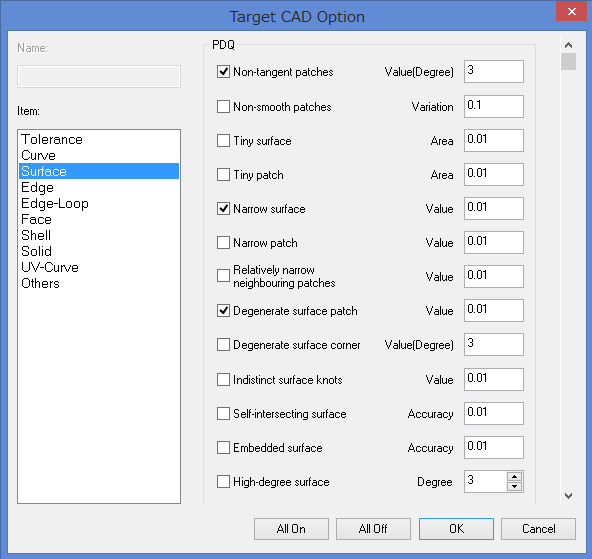
Guidelines for detecting surface errors were established by JAMA/JAPIA around 2001.
The main errors are as follows.
- Non-tangent patches
- Tiny patch
- Indistinct surface patches
- Degenerate surface patch
- Narrow surface
- Self-Intersecting surface
- Folded surface
- Wavy surface
- Small surface radius of curvature
With these check items, surface errors can be detected from a variety of viewpoints, but their visual representation (ease of identification) may be somewhat difficult to understand.
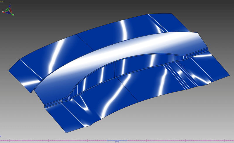
Zebra mapping
Zebra mapping (zebra shading) is probably used the most often in order to facilitate visual identification.
Subtle surface deformations can be confirmed by zebra mapping display as well, but this requires experience and appropriate settings of parameters. Because the display results vary according to the view rotation, there is a risk of overlooking problem areas.
Color mapping display according to curvature variations
When surfaces are polygonized and curvature variations of points on surface is displayed in color map, the display results will not vary according to the view rotation. Therefore, this method reduces the risk of overlooking problem areas.
There are two methods to view curvature variations: one is to look at across-the-board curvature distribution, and the other way is to specify a direction.
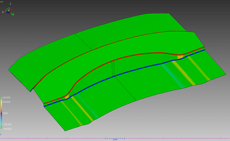
This method is effective for identifying the unevenness of the whole model.
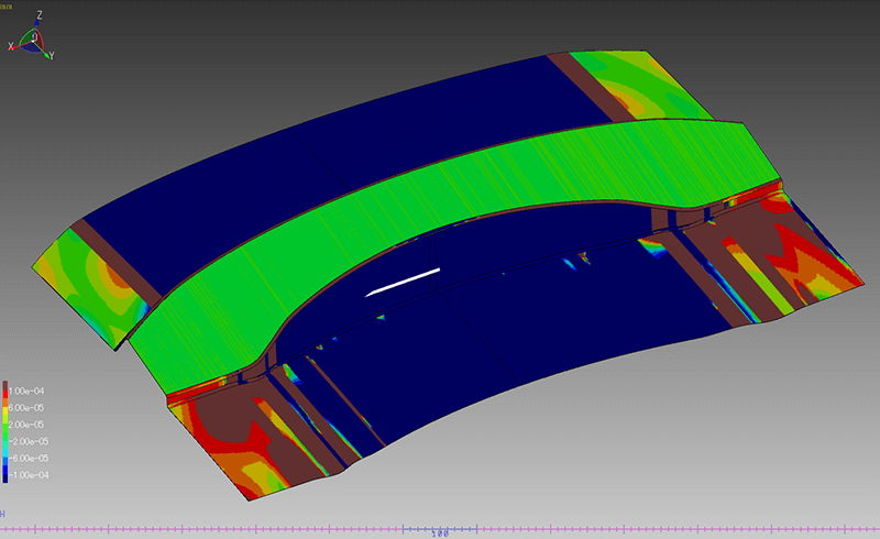
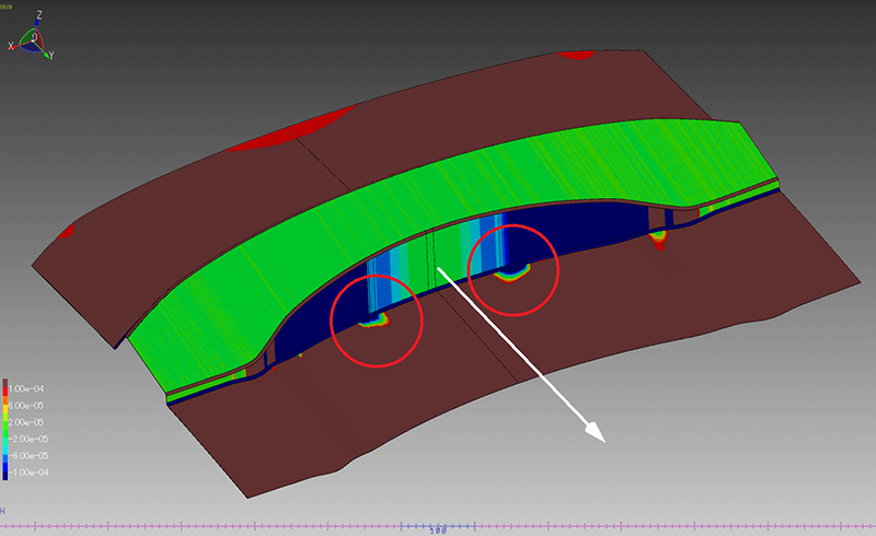
Using this method, subtle surface deformations that are not detected along the X-axis direction can be detected along the Y-axis direction.
Models are not necessarily always created in parallel with the base axis. For that, there is also a method to detect along a horizontal direction of current view. It is also possible to display the curvature variations of optional direction in color map by using view rotation well.
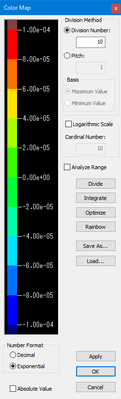
Setting parameter of color map essential for curvature display
A variety of methods are available to detect the locations of subtle surface deformations.
Each method has advantages and disadvantages, but the most important thing is the setting parameter. Determining appropriate parameters in accordance with the size and the surface quality of the target CAD model is important.
tag : Verification