


Features
Determine the Deformation and Positional Shift of Each Assembly Part Based on the Phenomena and the Expertise in Order to Establish the Countermeasure
Defects may be found during inspection when multiple components are assembled through assembly or welding even if the individual parts were created within allowable accuracy.
For rigid bodies (objects whose shape does not change), positional shifts (movement and rotation) caused by their assembly position can be occurred, and for elastic bodies (objects whose shape can change), part deformations can be occurred.
spGauge has a tool for visualizing deformation and displacement of each part after assembly.
Assembly evaluation function
- Use a non-contact measuring device to measure the surface assembled.
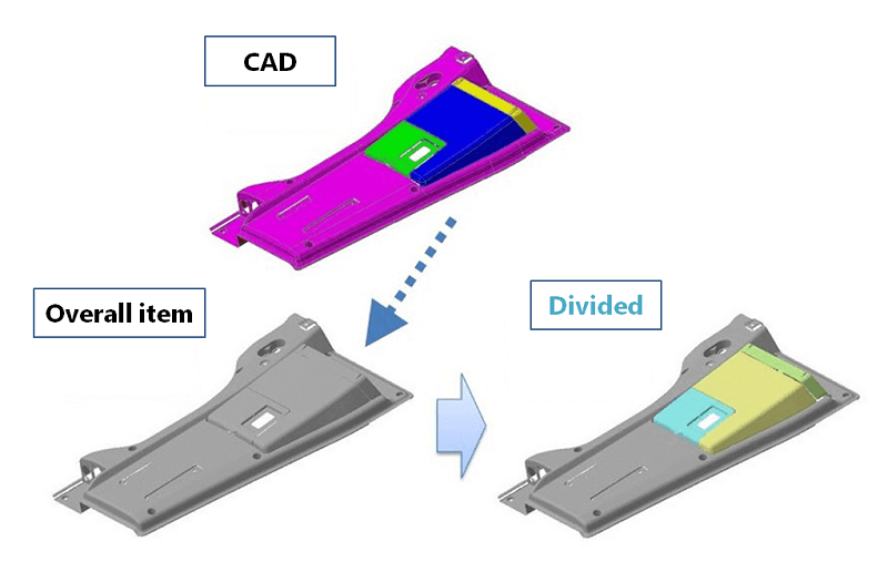
- Use spGauge to divide the overall point cloud data into point cloud data for each part surface.
This enables deformation analysis for individual parts. - The best fit between the point cloud data and the CAD data is determined for each divided part.
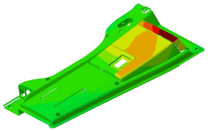
The parts deformed by the effect of assembly can be checked through color mapping.
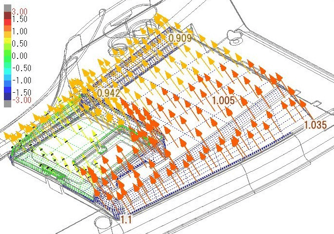
For the parts that are not deformed, a duplicate CAD data is created at the divided surface point cloud data locations, allowing to visualize the positional shift.
Deformation visualization
The best fit for the point cloud data of each divided component and the CAD data surfaces is determined, and deformations can be visualized through shape inspection (error color mapping).
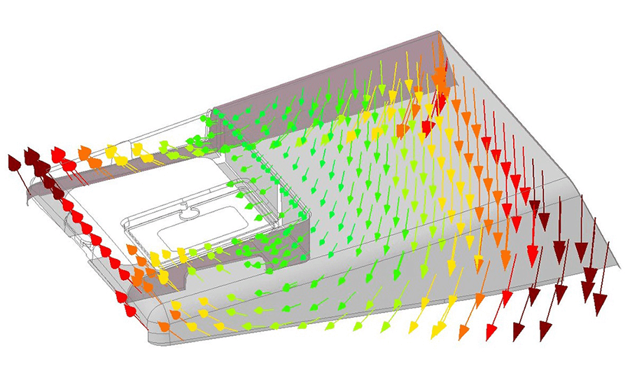
Positional shift visualization
Arrows showing the direction of the vector shifted from the original CAD data are displayed on CAD data duplicated on the surface point cloud data position. The degree of positional shifts can be displayed as a numerical value.
tag : Assembly evaluation