


Features
Before and After the Design Changes is Made Obvious

To check for differences in design modification between before and after takes much labor.
Using spGate, you can compare two CAD models and see the modified parts in different colors for easy review.
Changes such as a shift in hole locations, existence of taper and draft angle, and changes in panel-thickness are plainly seen. By specifying the tolerance value, even high precision checks such as in the order of submicron (0.1μm) is possible.
Display control for the surface difference result and the edge difference
Performing a visual check for differences before and after design changes (with shading display) is a burdensome task.
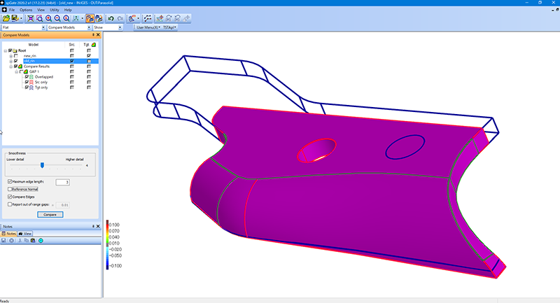
spGate can import two models created before and after design changes allowing you to easily check for differences.
The results from the difference check for “the difference results between surfaces” and “edge differences” can be controlled separately, allowing you to reliably check for slight differences.
Free to set the surface difference results
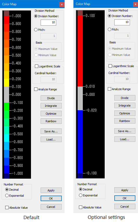
The default color map is set to equal intervals, but it can be freely set and saved.
The optional settings below have range errors from -0.02 mm to +0.01 displayed as gray. In this example, gaps of -0.02 mm or less are set to be blue, and gaps of +0.01 mm or more are set to be red.
Display control for the surface difference result
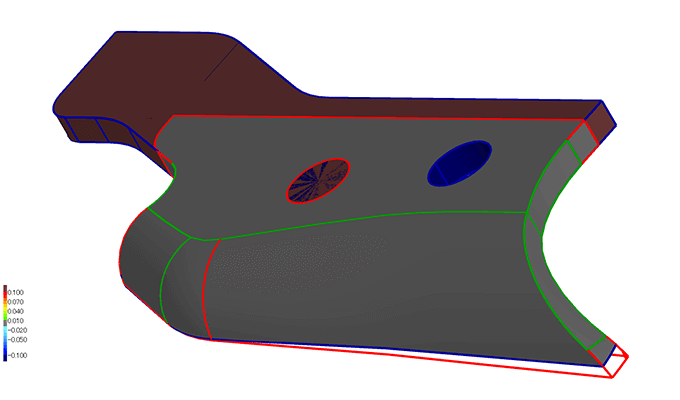
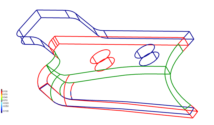
The difference results for “the difference results between surfaces” and “edge differences” can be displayed separately.
For example, as seen below, it is easy to check the differences in the surface configuration between two models by setting to hide “the difference result between surfaces” and display only “edge.”
The green edge is the edges existing in both models: the source and the target.
The red edge is the edges existing only in the source.
The yellow edge is the edges existing only in the target.
tag : Verification Compare models