


Use cases
Converting CAE (Spring-Back) Estimated Shapes to CAD Data
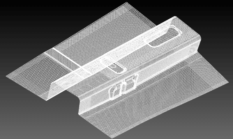
Here is an example of spScan reverse engineering utilized to convert CAE analysis data into CAD data.
Analysis data output from press mold forming simulation software (CAE) needs to be converted into polygon CAD surface data in order to be used as polygon mesh data (STL) in CAD, CAM, and CAE software.
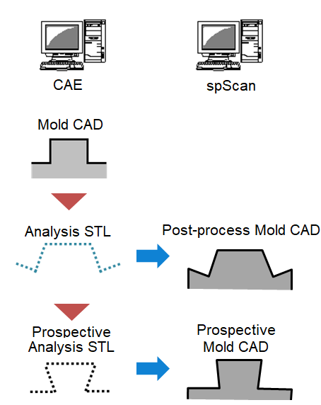
For the purposes of utilizing CAE analysis and shortening of the mold creation period, how to convert efficiently the analysis polygon mesh data to CAD surface using CAD software is important.
Reverse engineering of CAE analysis data
Apply multiple reverse engineering methods, such as partial reverse engineering offered by spScan, a program specifically for reverse engineering, and use the polygon mesh data from the estimated surface analysis results from the die’s CAD shape to create CAD surface data for the estimated mold.
Shortening mold creation lead time
- By converting estimated polygon meshes needed for CAE analysis to 3D CAD surfaces and carrying out CAE analysis again with 3D CAD surfaces of the estimated mold, you can verify whether the initial estimated value is correct or not.
- Furthermore, if the estimation is incorrect, you can obtain the optimal estimated shape by conducting mold estimate analysis with CAE software again and by repeating the 3D CAD surface conversion and CAE analysis.
- By applying the shape data from a 3D CAD surface conversion using the CAE spring-back analysis results, it becomes possible to design the model with an estimated amount of spring-back deformation, and the man-hours required for correction of the mold can be reduced.
- By applying the partial reverse engineering method, it became possible to perform reverse engineering in a short amount of time.